
XLR Panel Sockets Types: Mixer and Amplifier Installation Guide
XLR panel sockets are essential components in professional audio systems, providing reliable balanced connections between mixers, amplifiers, and other audio equipment. This guide covers the different types of XLR panel sockets available, their specifications, and proper installation procedures for mixer and amplifier applications. Understanding these components helps audio professionals and hobbyists create stable signal chains with minimal interference and optimal audio quality.
Understanding XLR Panel Socket Basics
XLR panel sockets serve as the female connector interface mounted on equipment chassis. These sockets accept XLR plugs from cables and provide the connection point for audio signals to enter or exit devices. The panel-mount design allows for secure attachment to equipment enclosures while providing a durable connection point that withstands repeated use in professional environments. XLR sockets are rated for thousands of connection cycles without significant degradation when properly maintained.
Three-pin XLR sockets dominate the audio industry due to the balanced audio connection standard. Balanced connections use two signal conductors and a ground, allowing for noise rejection over long cable runs. This makes three-pin XLR sockets the foundation of most mixer and amplifier installations. The International Electrotechnical Commission maintains standards for XLR connector specifications that ensure interoperability between manufacturers.
XLR Panel Socket Types and Configurations
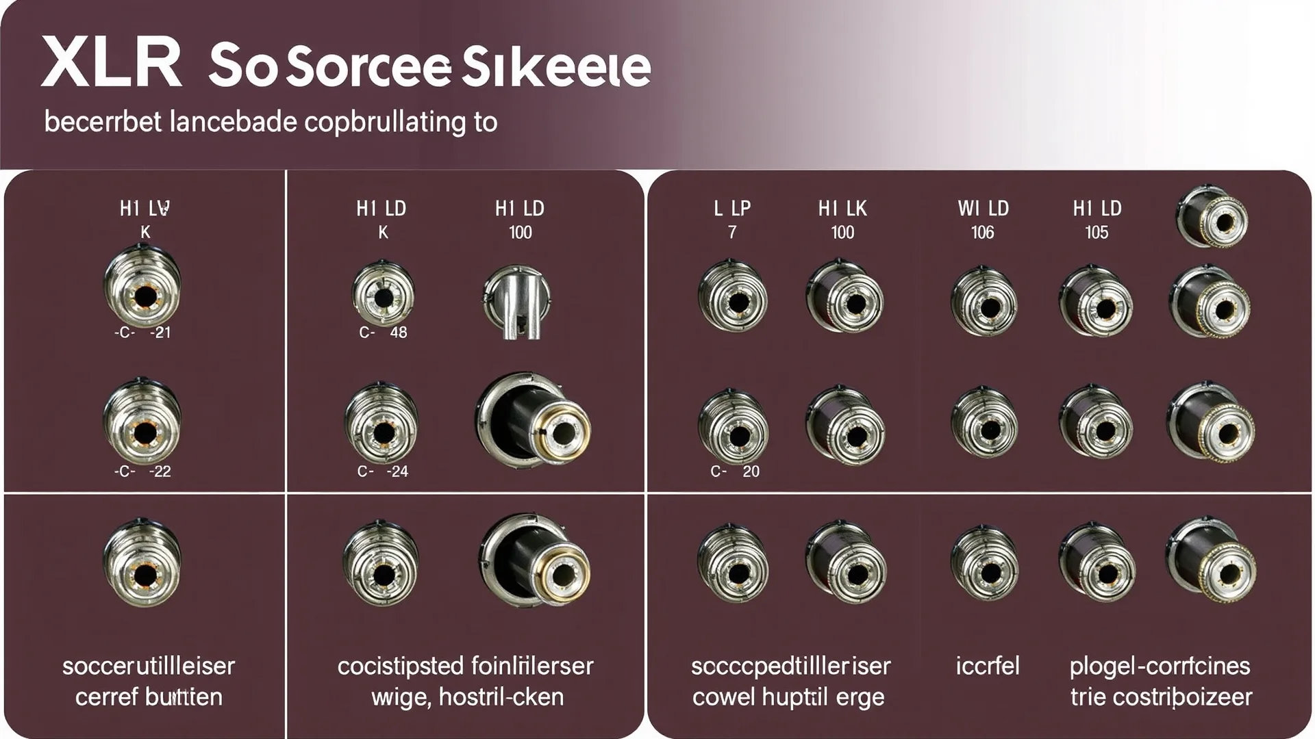
XLR panel sockets come in several configurations suited for different audio applications. The most common types include three-pin, four-pin, five-pin, and in some cases six-pin variants. Three-pin XLR remains the industry standard for audio mixing and amplification systems. Four-pin XLR commonly serves lighting equipment and intercom systems. Five-pin XLR handles three-channel balanced connections found in some professional installations.
Socket mounting styles vary to accommodate different panel types and installation requirements. The standard flange mount provides a flat surface for attachment, while threaded bushings allow for secure mounting in equipment racks. Some sockets include switch contacts that detect plug insertion, useful for automatic signal routing or muting circuits. Understanding these variations helps select the appropriate socket for each specific installation scenario.
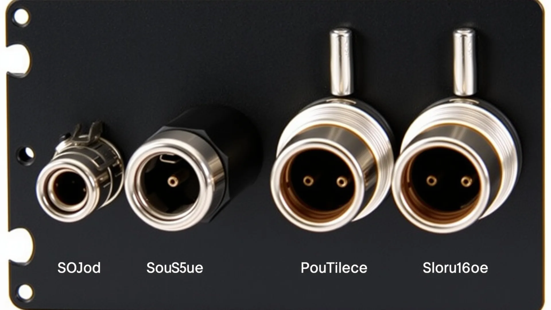
Choosing between male and female panel sockets depends on signal flow direction. Audio mixers typically output through male panel connectors while amplifiers receive input through female panel sockets. This convention simplifies signal routing and reduces connection errors. However, some installations may reverse this configuration depending on equipment layout and signal flow requirements.
Mixer Installation Guidelines
Mixer installation begins with identifying signal input and output requirements. Each channel strip on a mixer requires a balanced input socket, typically an XLR female panel socket wired for dynamic or condenser microphone connection. Professional mixers provide 48-volt phantom power through these sockets for condenser microphones. This power travels on pins 1 and 2, with pin 1 serving as ground reference throughout the signal chain.
Insert points on mixers use specialized sockets that combine input and output connections in a single housing. These allow external processors like compressors or equalizers to interface with specific mixer channels. The ring contact carries the output signal to the processor while the tip contact returns the processed signal to the mixer. This design maintains balanced connectivity throughout the external processing chain.
Master output sockets on mixing consoles typically employ male XLR panel connectors. These carry the final mixed signal to amplifiers, recording devices, or additional mixing consoles. The output level from these sockets usually ranges from -10 dBV to +4 dBu depending on console design. Matching output levels to amplifier input sensitivity ensures optimal signal-to-noise ratio and prevents distortion.
Amplifier Connection Procedures
Power amplifiers receive audio signals through female XLR panel sockets mounted on their rear panels. The signal enters through pin 2 (hot) and pin 3 (cold), with pin 1 providing shield ground connection at both ends. Proper polarity maintains signal phase through the entire audio chain. Inverting phase accidentally results in thin, hollow sound quality that undermines mix integrity.
Input sensitivity settings on amplifiers determine how much input signal drives the amplifier to full power. Most professional amplifiers offer sensitivity settings of 0.775 volts, 1.4 volts, or variable settings. Matching sensitivity to the connected mixer’s output level optimizes headroom and prevents overdriving the amplifier input stage. Reference the amplifier documentation for specific sensitivity adjustment procedures.
Link or throughput sockets on amplifiers allow daisy-chaining signals to additional amplifiers without using splitter cables. These parallel the main input socket and maintain signal integrity through the chain. This configuration suits multi-amplifier setups common in large venue installations where multiple amplifier zones require the same source signal.
Wiring Standards and Best Practices
XLR wiring follows a standardized pinout adopted across the audio industry. Pin 1 connects to the connector shell and cable shield, providing the grounding path. Pin 2 carries the positive polarity audio signal, often called the hot or positive leg. Pin 3 carries the negative polarity audio signal, referred to as the cold or negative leg. Consistent wiring across all connections ensures proper signal polarity throughout the system.
Cable selection significantly impacts system performance and reliability. Microphone cables provide excellent shielding and flexibility for connecting mixers to amplifiers. These cables typically use 20-22 AWG conductors with braided or spiral shields that provide superior noise rejection compared to power cables running in proximity. Quality cables reduce ground loop problems and electromagnetic interference.
Alternative cable types serve specific installation needs. Flat cables suit permanent installations where cables run through tight spaces or under carpeting. Instrument cables work for unbalanced connections when distance limitations prevent ground loop issues. DMX cables serve lighting control applications that sometimes share infrastructure with audio systems in professional venues.
Network integration expands in modern audio installations. Ethernet cables increasingly carry digital audio protocols like Dante or AVB between network-enabled equipment. Network cable extenders overcome distance limitations of standard ethernet runs. These digital alternatives supplement rather than replace traditional XLR connections in most installations.
Troubleshooting Common Installation Issues
Ground loops cause unwanted hum and buzzing in audio systems when multiple grounding points exist at different potentials. This commonly occurs when connecting equipment powered from different electrical circuits. Breaking the signal ground at one connection point using a ground lift adapter often resolves hum issues. However, lifting grounds can increase susceptibility to RF interference in some environments.
Signal loss over long cable runs results from cable resistance and capacitance degrading high-frequency response. Balanced connections handle longer runs better than unbalanced connections due to common-mode noise rejection. For runs exceeding 100 meters, consider using line drivers or digital audio transmission systems that regenerate the signal without quality loss.
Loose panel socket connections produce intermittent signals or complete signal dropout. Vibration and repeated plugging gradually loosen socket contacts. Inspecting sockets with a flashlight reveals worn or damaged contacts. Replacing worn sockets prevents unreliable connections that compromise live performances or recording sessions. Professional installations schedule preventive maintenance to check all connection points periodically.
Safety Considerations and Standards
Audio equipment grounding requires careful attention to prevent shock hazards and ensure proper shielding effectiveness. National Electrical Code standards govern equipment grounding requirements for commercial audio installations. Professional installers understand local code requirements and ensure compliance for venue safety and insurance purposes.
Peak voltage levels in amplifier outputs far exceed safe touch voltages when driving low-impedance loads. Installing XLR connections on amplifier output panels keeps these hazardous connections contained within equipment designed for such voltages. Never route speaker-level signals through XLR cables not rated for the current involved. Reference ISO standards for audio equipment safety when planning installations.
Equipment rack mounting practices affect both safety and system longevity. Secure mounting prevents equipment damage from falling and reduces strain on panel connections. Allow adequate ventilation for heat-producing equipment like amplifiers. Following industry safety guidelines protects personnel and equipment during operation and maintenance.
Summary and Key Takeaways
XLR panel sockets provide the standardized connection interface that enables reliable audio signal routing in professional and consumer installations. Three-pin female sockets serve as the primary input connectors on amplifiers, accepting signals from mixer outputs through male XLR plugs. Understanding pin assignments and wiring polarity ensures proper signal phase throughout the audio chain.
Proper installation techniques prevent common problems like ground loops, signal loss, and connection failures. Using appropriate cable types for each application and following manufacturer recommendations maintains system reliability. Regular inspection and maintenance of panel sockets and connections extends equipment life and prevents failures during critical use.
Modern installations increasingly incorporate digital audio networking alongside traditional analog connections. Understanding both analog XLR infrastructure and digital alternatives helps audio professionals design systems suited to current and future requirements. Reference accessibility standards when installing equipment in public venues to ensure compliance with relevant regulations.
Frequently Asked Questions
What is the difference between XLR3 and XLR5 panel sockets?
XLR3 sockets have three pins and carry a single balanced audio channel. XLR5 sockets have five pins and can carry two separate balanced channels or a stereo balanced connection. XLR3 remains the standard for most mixer and amplifier applications.
Can I use microphone cables for amplifier connections?
Yes, microphone cables work for connecting mixer outputs to amplifier inputs because both use the same three-pin XLR format and balanced wiring. However, ensure cables are rated for the signal levels involved in your specific installation.
Why does my amplifier produce hum when connected to my mixer?
Ground loops typically cause hum when equipment grounds at different potentials. Try lifting the ground at the amplifier input using a ground lift adapter, or ensure all equipment shares a common electrical ground circuit.
How do I wire an XLR panel socket?
Wire pin 1 to the cable shield, pin 2 to the hot or positive conductor, and pin 3 to the cold or negative conductor. Maintain consistent wiring throughout the entire signal chain to preserve signal polarity and phase.
What cable type suits permanent amplifier installations?
Flat cables work well for permanent installations where cables run under floors or through tight spaces. For standard rack-to-rack connections, flexible shielded cables provide durability and ease of maintenance during system adjustments.


