
Clean audio depends as much on cable setup as on microphones, mixers, or speakers. Noise and interference can enter a signal through electromagnetic fields, radio-frequency sources, poor shielding, bad routing, or grounding problems, often becoming more obvious once low-level signals are amplified. This article explains where that unwanted noise comes from, how different cable designs resist it, and which installation choices make the biggest difference in real systems. By the end, you’ll have a practical framework for reducing hum, buzz, and hiss in audio cables before they compromise recording quality or live sound performance.
Why audio cables still face noise and interference
Despite advancements in digital audio networking, analog audio cables remain the critical interface between transducers, preamplifiers, and distribution systems. The fundamental challenge lies in the physical properties of analog signal transmission, where the audio payload is represented by continuous voltage fluctuations. Because these voltages are often minuscule—microphone-level signals typically range from -60 dBV to -40 dBV (1 millivolt to 10 millivolts)—even microvolts of induced noise can severely compromise the signal-to-noise ratio (SNR) once amplified.
To engineer systems with pristine audio fidelity, industry professionals must understand the mechanisms by which external electromagnetic forces interact with cable geometries. Mitigating noise requires a systematic approach to identifying interference vectors, anticipating environmental hazards, and deploying infrastructure engineered to reject unwanted artifacts.
Common sources of noise and signal degradation
Signal degradation in audio cables originates from three primary vectors: electromagnetic interference (EMI), radio frequency interference (RFI), and ground loops. EMI is typically generated by inductive coupling from nearby alternating current (AC) sources, resulting in a pervasive 50 Hz or 60 Hz hum. When power lines and audio cables run parallel, the magnetic field from the power source induces an unwanted current in the audio conductors.
RFI presents as high-frequency noise introduced by wireless transmitters, cellular networks, and digital clocks. Operating in bands from 100 MHz up to 5 GHz, RFI can penetrate poorly shielded cables, where it is often demodulated by the nonlinear junctions of preamplifier input stages, manifesting as audible static or radio broadcasts. Additionally, ground loops occur when interconnected equipment references different ground potentials, causing stray currents to flow through the audio cable’s shield.
Environments with the highest interference risk
Certain operational environments exacerbate the risk of interference, demanding highly specialized cable deployments. Live performance stages and theatrical venues represent exceptionally hostile environments due to the dense concentration of lighting dimmers. Silicon-controlled rectifier (SCR) dimmers chop AC waveforms, generating aggressive harmonic transients that easily induce broadband noise into adjacent microphone lines.
Industrial facilities, broadcast studios, and medical environments also present severe EMI/RFI challenges. In these settings, variable frequency drives (VFDs), heavy machinery, and MRI equipment generate massive magnetic fields. To maintain a Total Harmonic Distortion plus Noise (THD+N) threshold below the professional standard of 0.001%, infrastructure in these environments necessitates cables with maximum shielding density, precise twist rates, and rigorous isolation protocols.
Audio cable specifications that matter most
Specifying the correct audio cables requires analyzing objective electrical properties rather than relying on subjective audio claims. The fundamental parameters defining cable performance are capacitance, impedance, conductor resistance, and shielding topology. Low capacitance, typically measured between 20 pF/ft and 30 pF/ft (picofarads per foot), is critical to prevent the cable from acting as a low-pass filter, which would cause high-frequency roll-off over long runs.
Conductor purity and geometry also play a vital role. Professional-grade cables utilize Oxygen-Free Copper (OFC) refined to 99.99% purity to minimize resistance and prevent internal oxidation over decades of use. Understanding how these specifications interact allows system integrators to match the exact cable architecture to the intended application.
Balanced vs unbalanced cable performance
The distinction between balanced and unbalanced architectures is the most critical factor in noise rejection. Unbalanced cables utilize a single central conductor for the signal and an outer shield that doubles as the signal return path. This design leaves the audio payload entirely vulnerable to any EMI or RFI that breaches the shield.
Balanced audio cables utilize two dedicated signal conductors (often designated ‘hot’ and ‘cold’) inverted in phase, enveloped by a separate grounded shield. When the signal reaches a differential input stage, the phase of the ‘cold’ line is flipped. The original audio signals combine, while any noise induced equally on both conductors is phase-canceled—a principle measured as the Common-Mode Rejection Ratio (CMRR). High-quality balanced inputs can achieve a CMRR of 80 dB or higher, effectively eliminating induced noise.
| Specification | Balanced Audio Cables | Unbalanced Audio Cables |
|---|---|---|
| Conductor Configuration | Two signal conductors (hot/cold) + shield | One signal conductor + shield/ground |
| Maximum Effective Run Length | > 100 meters (300+ feet) | < 6 meters (20 feet) |
| Common-Mode Rejection (CMRR) | High (Typically 50 dB to 80+ dB) | None (0 dB) |
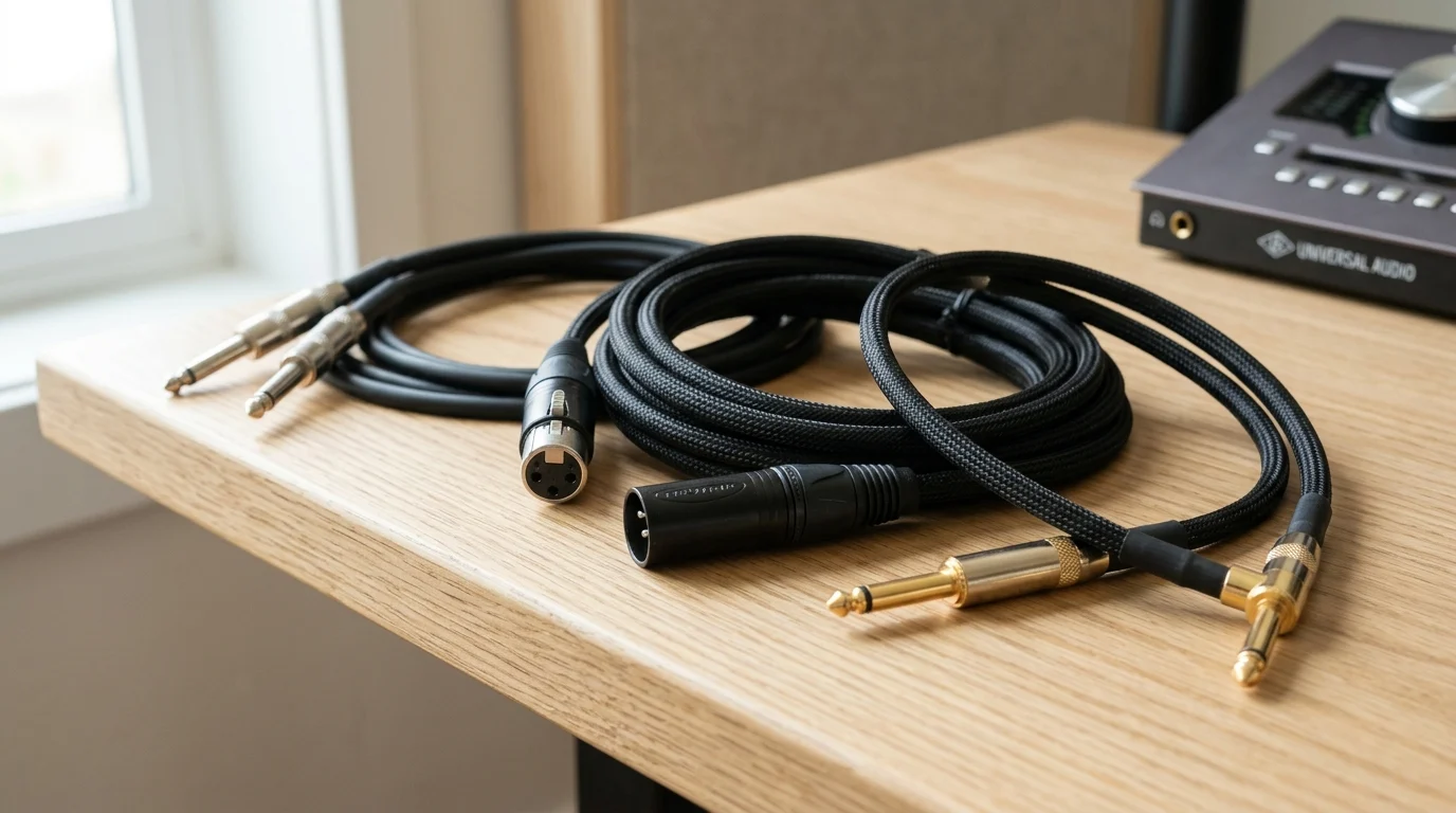
| Typical Connectors | XLR, TRS (Tip-Ring-Sleeve) | RCA, TS (Tip-Sleeve) |
| Primary Application | Microphones, professional line-level runs | Instruments, consumer audio equipment |
Shielding, conductors, and connector design
Shielding construction dictates a cable’s immunity to specific interference types. Braided copper shields offer excellent structural integrity and up to 95% coverage, making them ideal for low-frequency EMI rejection and applications requiring high flexibility. Foil shields (aluminum Mylar) provide 100% coverage, excelling at high-frequency RFI rejection, but are mechanically fragile and strictly suited for permanent, fixed installations. Spiral (serve) shields offer a compromise, providing high flexibility and roughly 90% coverage for moderate-risk environments.
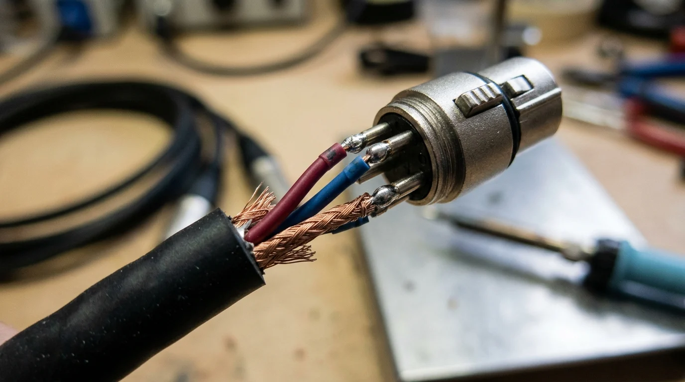
Connector design is equally important to the signal chain’s integrity. Connectors utilizing solid machined brass contacts with 2-micron to 5-micron gold plating provide superior resistance to galvanic corrosion in humid environments. Furthermore, robust connector housings with internal chuck-type strain relief prevent mechanical stress from degrading the solder joints, which is a primary cause of intermittent static and microphonics.
Cable types for microphone, instrument, and line-level signals
Microphone cables transport low-voltage, low-impedance (150 Ω to 600 Ω) signals over long distances, necessitating balanced designs with tight conductor twisting (short lay lengths) to maximize common-mode rejection. The precision of the twist directly correlates to the cable’s ability to reject magnetic interference.
Instrument cables, conversely, handle high-impedance signals (up to 1 MΩ) from passive guitar pickups. This high impedance makes them highly susceptible to triboelectric noise—handling noise caused by friction between the dielectric and the shield when the cable is moved. To combat this, premium instrument cables incorporate a conductive PVC sub-shield between the dielectric and the primary copper shield to dissipate static charges.
Line-level cables transmit much higher voltages (commonly +4 dBu or -10 dBV) and are consequently less sensitive to subtle induced noise. However, in dense rack wiring, line-level interconnects still require robust shielding and low capacitance to maintain phase coherency and prevent crosstalk between adjacent channels.
Installation practices that minimize interference
Even cables engineered with the highest specifications will fail to deliver pristine audio if subjected to poor installation practices. The physical deployment methodology directly influences the system’s susceptibility to inductive and capacitive coupling. Proper infrastructure design relies on strict adherence to spatial geometry, rigorous grounding protocols, and meticulous termination standards.
Industry best practices dictate that physical separation is the most effective defense against magnetic interference, governed by the inverse-square law. Maintaining a minimum physical separation of 12 inches (30 cm) between parallel analog audio lines and high-voltage AC power conduits is a mandatory threshold for professional installations.
Routing, separation, grounding, and cable management
Routing pathways must be engineered to isolate sensitive audio lines from aggressive power infrastructure. When audio cables and power conduits must intersect, they should cross at exact 90-degree angles to minimize the inductive coupling footprint. Long parallel runs must be avoided entirely. In structured cabling environments, utilizing distinct, physically separated cable trays for high-voltage, low-voltage digital, and low-voltage analog lines is standard practice.
Grounding topologies must be designed to prevent the circulation of stray currents. Implementing a strict star grounding system, where all audio equipment references a single, unified earth ground point, drastically reduces the potential for ground loops. Cable management within racks should avoid tightly bundling disparate signal types; instead, installers should segregate bundles by signal level (mic, line, speaker, and power) and secure them loosely to prevent dielectric deformation.
Termination, bonding, strain relief, and connector maintenance
Termination integrity defines the mechanical and electrical reliability of the cable assembly. Cold solder joints or oxidized conductors introduce series resistance and diode-like rectification, which can demodulate RFI into the audible spectrum. Professional termination requires temperature-controlled soldering stations and eutectic solder alloys to ensure low-impedance bonding.
Installers must adhere strictly to the AES48 standard, which mandates that the cable shield (pin 1 on an XLR connector) must be tied directly to the equipment chassis ground, not the internal audio signal ground. This diverts external RF energy away from the sensitive preamplifier circuitry. Additionally, managing bend radius is critical; cables should never be subjected to a bend radius tighter than 4 to 10 times their outer diameter (depending on the jacket material) to prevent structural damage to the shield and dielectric.
Step-by-step troubleshooting for hum, buzz, and RF noise
When hum, buzz, or RF noise infiltrates a system, troubleshooting must follow a sequential, isolation-based methodology. The first step in diagnosing a 60 Hz hum is to utilize a ground lift switch on the receiving equipment. If lifting the audio ground eliminates the hum, a ground loop is confirmed. However, safety grounds on AC power cables must never be lifted under any circumstances, as this creates a lethal electrocution hazard.
If ground loops persist across disparate power zones, installers should deploy high-quality isolation transformers. A 1:1 ratio audio isolation transformer magnetically couples the signal while completely severing the direct electrical connection, entirely breaking the ground loop. For persistent RFI, troubleshooting involves inspecting the integrity of all shield terminations, ensuring robust chassis bonding, and potentially installing ferrite chokes on the cable exterior to suppress high-frequency common-mode currents.
How to evaluate suppliers and make the right cable choice
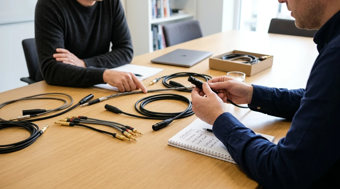
Procurement professionals and system integrators must evaluate cable suppliers based on empirical test data, manufacturing consistency, and supply chain transparency. Selecting the right audio cable transcends basic specifications; it requires assessing the Original Equipment Manufacturer’s (OEM) quality control infrastructure and material sourcing capabilities.
A reliable audio cable manufacturer should operate under ISO 9001 certified quality management systems and maintain a defect rate strictly below 0.1% (1000 Parts Per Million). By demanding rigorous documentation and understanding the material science behind cable construction, buyers can ensure long-term reliability and compliance with international installation codes.
Test data, certifications, and quality control checks
Suppliers must provide comprehensive test data to validate their specifications. Reputable manufacturers utilize Time-Domain Reflectometry (TDR) testing to ensure impedance uniformity across the entire length of a cable spool. Deviations in impedance cause signal reflections and phase anomalies, particularly in high-frequency digital audio transmission (such as AES3).
Furthermore, cables must carry appropriate certifications for the target market. Environmental compliance, such as RoHS (Restriction of Hazardous Substances) and REACH, is mandatory for global distribution. For fixed architectural installations, suppliers must provide cables with verified fire safety ratings. In the United States, the National Electrical Code (NEC) requires cables routed inside walls or plenums to carry UL CL2, CL3, or CMP ratings, ensuring the jacket materials will not propagate flames or emit highly toxic smoke during a fire.
Material and construction factors that affect durability
The choice of jacket material profoundly impacts the cable’s durability, flexibility, and environmental resistance. Standard Polyvinyl Chloride (PVC) jackets are cost-effective and suitable for general studio use. However, for touring and outdoor broadcast applications, Polyurethane (PUR) or Thermoplastic Elastomer (TPE) jackets are required. PUR offers exceptional abrasion resistance, UV stability, and remains flexible in sub-zero temperatures.
Internal construction factors, such as the inclusion of cotton or Kevlar filler yarns, prevent the internal conductors from stretching and migrating during repeated coiling. Suppliers servicing the live event industry should provide flex life testing data, demonstrating that their stage cables are engineered to withstand in excess of 50,000 continuous bend cycles without structural failure or degradation of the shielding coverage.
A decision framework for selecting the right cable
Selecting the optimal audio cable requires a structured decision framework that balances electrical performance, mechanical durability, and project budget. Integrators must map the specific environmental hazards of their project to the corresponding cable specifications.
| Evaluation Metric | Target Specification | Operational Impact |
|---|---|---|
| Shielding Coverage | > 95% for braided, 100% for foil | Determines baseline immunity to EMI and RFI in hostile environments. |
Key Takeaways
- The most important conclusions and rationale for Audio Cables
- Specs, compliance, and risk checks worth validating before you commit
- Practical next steps and caveats readers can apply immediately
Frequently Asked Questions
What is the most effective way to cut hum in audio cables?
Use balanced XLR or TRS cables, keep them away from AC power lines, and avoid long parallel runs. This greatly reduces 50/60 Hz induced hum.
When should I choose balanced instead of unbalanced cables?
Choose balanced for microphones, stage boxes, mixers, and runs over 6 meters. Use unbalanced only for short connections like nearby consumer RCA gear.
How can cable routing reduce interference on stage or in studios?
Separate audio and power cables, cross them at 90 degrees, and keep lines away from dimmers, adapters, and transformers. Clean routing often fixes buzz without changing gear.
Which cable features matter most for low-noise performance?
Look for dense shielding, twisted pair construction, low capacitance, and 99.99% OFC conductors. JINGYI premade and OEM/ODM cables are built for pro-audio noise control.
What should I do if a ground loop causes buzzing?
Power connected audio devices from the same outlet strip when possible, check grounding consistency, and use balanced connections. Do not lift safety earth on mains-powered equipment.


