
Introduction
Bi-amping with a 4-pole Speakon connector lets one cable carry separate low- and high-frequency amplifier outputs to a speaker, but the wiring must match the enclosure and amplifier channel assignment exactly. A wrong polarity or pin connection can send the wrong band to a driver, cause phase problems, or damage components under load. This guide explains the standard pin layout, how LF and HF channels are typically assigned across 1+/1- and 2+/2-, and what to verify before powering the system, so you can wire the connector confidently and avoid costly mistakes.
Why Correct Speakon Wiring Matters in Bi-Amped Systems
Bi-amping represents a critical methodology in professional audio reinforcement, bypassing passive crossover networks within loudspeaker enclosures in favor of active, upstream signal division. By utilizing active crossovers or digital signal processors (DSPs) to separate low and high frequencies before amplification, sound engineers achieve superior phase alignment, reduced intermodulation distortion, and optimized amplifier power allocation.
To deliver these discrete high-power signals to the loudspeaker enclosure efficiently, the 4-pole Speakon connector has become the industry standard. Proper termination and routing within this connector are paramount for system stability and acoustic performance.
Benefits of a 4-pole Speakon connector
Deploying a 4-pole Speakon connector allows audio technicians to consolidate two discrete amplifier channels—typically low-frequency (LF) and high-frequency (HF)—into a single multi-conductor cable. This 50% reduction in cable deployment minimizes stage clutter, reduces copper weight in touring rigs, and streamlines patching logistics.
Furthermore, industry-standard 4-pole connectors boast a continuous current rating of up to 30A RMS (or 40A for audio signals at a 50% duty cycle). This high-current capacity ensures the connectors can handle the immense power requirements of modern subwoofers and mid-high arrays without introducing signal degradation, voltage drops, or thermal failure.
Risks of incorrect wiring
The primary risk of incorrect wiring in a bi-amped configuration is catastrophic transducer failure. Because active bi-amping removes the protective passive crossover components inside the speaker cabinet, the delicate voice coils are directly coupled to the amplifier outputs.
If an assembly error routes a 1000W low-frequency signal (e.g., 40 Hz to 1.2 kHz) into a fragile high-frequency compression driver rated for a 1.5 kHz minimum crossover point, the diaphragm will over-excurse and burn out almost instantaneously. Additionally, reversing polarity on one frequency band will create severe phase cancellations at the acoustic crossover point, resulting in destructive interference and massive dips in the system’s frequency response.
Standard 4-Pole Speakon Pinout for Bi-Amping
Establishing a universal pinout standard is essential for cross-compatibility between different rental houses, touring productions, and venue installations. The 4-pole Speakon connector utilizes four discrete contact points labeled 1+, 1-, 2+, and 2-. While the physical architecture of the connector allows for any arbitrary routing, deviating from established norms drastically increases the probability of equipment damage during high-pressure load-ins.
Typical assignments for 1+, 1-, 2+, and 2
In the majority of professional bi-amped systems, the industry-standard pinout assigns the low-frequency (LF) or mid-low signal to pins 1+ and 1-, while the high-frequency (HF) signal is assigned to pins 2+ and 2-.
This convention ensures that if a standard 2-pole cable (which only connects to 1+/1-) is accidentally used, it will safely drive only the robust LF section of the speaker. This fail-safe leaves the sensitive HF driver unpowered, rather than subjecting it to full-range or incorrect low-frequency signals that would cause immediate mechanical failure.
| Application Type | Pins 1+ / 1- | Pins 2+ / 2- | Typical Cable Gauge |
|---|---|---|---|
| Standard Bi-Amp Top | Low Frequency (LF) | High Frequency (HF) | 4 x 2.5 mm² (13 AWG) |
| Passive Subwoofer | Subwoofer Signal | Pass-through to Tops | 4 x 4.0 mm² (11 AWG) |
| Dual Subwoofer | Subwoofer Driver 1 | Subwoofer Driver 2 | 4 x 4.0 mm² (11 AWG) |
When to follow manufacturer pinout conventions
Despite the prevalence of the standard 1+/1- (LF) and 2+/2- (HF) convention, top-tier loudspeaker manufacturers frequently engineer proprietary pinout schemes to facilitate specific system topologies. For example, certain manufacturers configure their subwoofers to receive signals exclusively on pins 2+ and 2-, utilizing pins 1+ and 1- as a direct pass-through.
This topology allows a single 4-pole cable to carry both the subwoofer and top-box signals from the amplifier rack; the subwoofer taps the 2-pole signal it requires and passes the 1-pole signal onward to the mid-high enclosures. System technicians must consult technical documentation for specific impedance loads—such as parallel 8-ohm drivers presenting a 4-ohm load to the amplifier—and verify proprietary pinouts prior to integrating mixed-brand equipment.
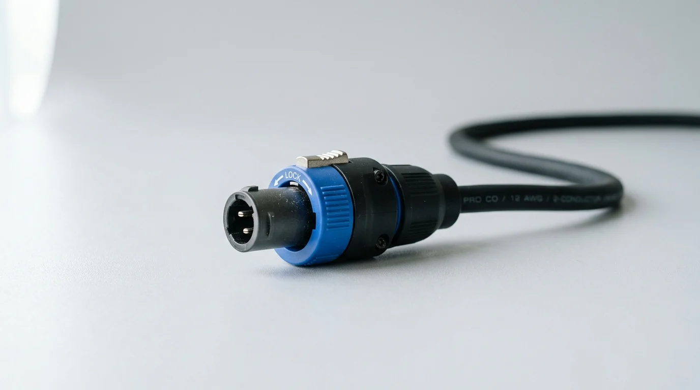
How to Wire a 4-Pole Speakon Connector for Bi-Amping
Proper assembly of a 4-pole Speakon connector requires precision and adherence to manufacturer specifications to ensure maximum contact surface area and secure mechanical retention. The connector relies on a unique twist-lock mechanism and a multi-part internal assembly, which includes the outer housing, the contact insert, a chuck-type strain relief, and a threaded bushing.
Tools, cable types, and conductor gauges
For professional bi-amping, utilize a high-quality 4-conductor speaker cable. Standard deployments typically rely on 4 x 2.5 mm² (13 AWG) conductors for runs up to 15 meters, while longer runs or high-draw subwoofers demand 4 x 4.0 mm² (11 AWG) copper to minimize insertion loss and preserve the amplifier’s damping factor.
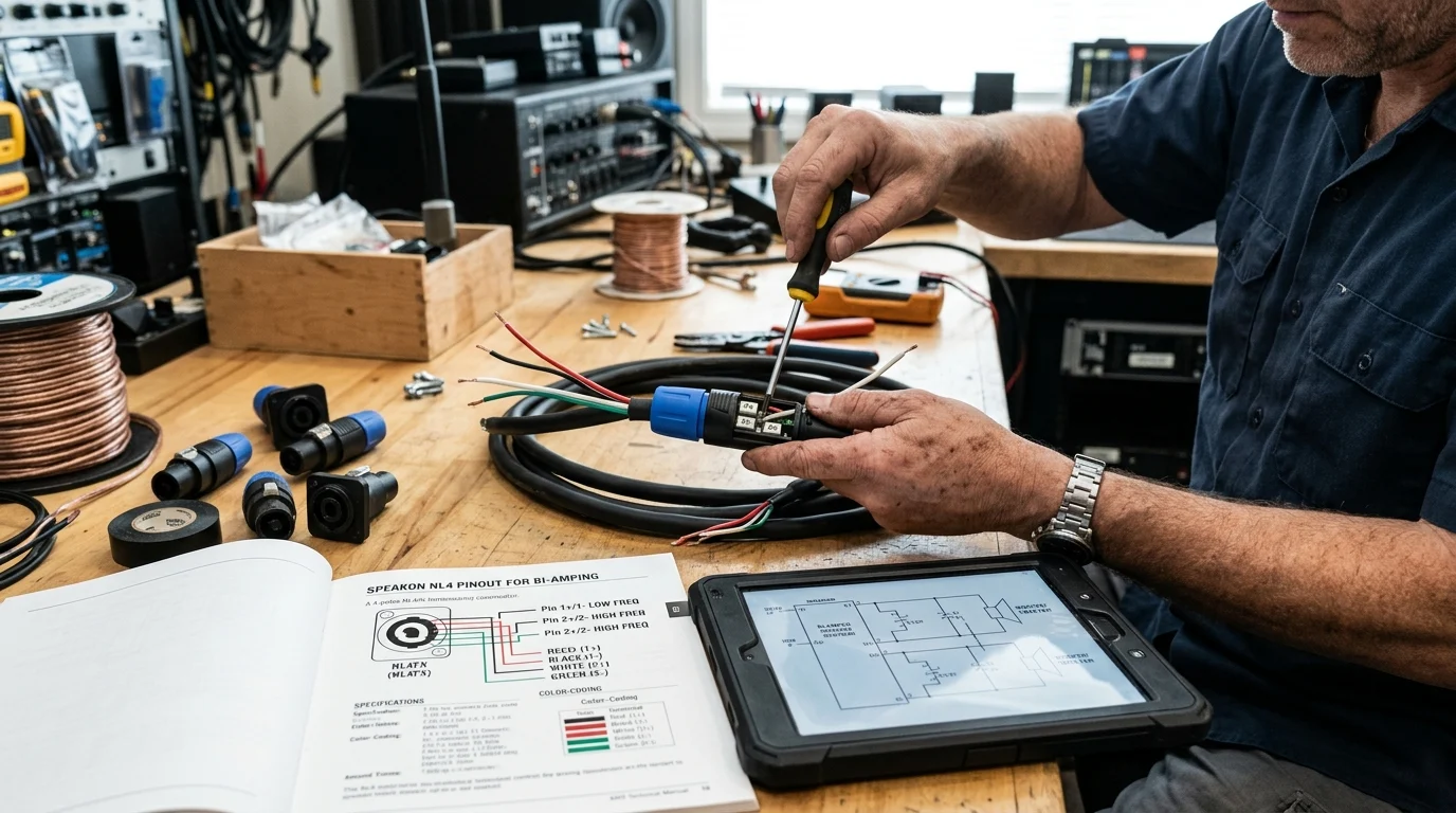
To prepare the cable, strip back exactly 20 mm of the outer PVC jacket, taking care not to nick the internal conductor insulation. Subsequently, strip 8 mm of insulation from each of the four individual conductors. A Pozidriv #1 (PZ1) screwdriver is strictly recommended over a standard Phillips head, as the PZ1 provides the optimal torque (typically 0.8 Nm) to secure the screw terminals without stripping the heads or failing to compress the copper strands adequately.
Polarity, strain relief, and continuity checks
Before finalizing the assembly, verify polarity by ensuring the color-coded conductors match identically at both ends of the cable (e.g., Red to 1+, Black to 1-, White to 2+, Green to 2-). Slide the chuck-type strain relief over the conductors; this component is engineered to grip outer cable diameters ranging from 7 mm to 14.5 mm securely.
Once the threaded bushing is tightened, the strain relief prevents mechanical tension from reaching the electrical contacts. Finally, perform a continuity check using a digital multimeter. The end-to-end resistance on each pole should measure less than 0.1 ohms, and there must be infinite resistance (open circuit) between adjacent poles to confirm no stray copper strands are causing an internal short circuit.
2-Pole vs 4-Pole Speakon Connectors
While 2-pole and 4-pole Speakon connectors share a nearly identical external footprint, their internal architecture and application scopes differ significantly. Understanding the mechanical and electrical distinctions between the NL2 and NL4 formats is crucial for system integrators managing inventory and deploying complex audio networks.
Key differences in bi-amp applications
The primary difference lies in the contact density. A 2-pole connector (NL2) is equipped strictly with 1+ and 1- contacts, making it suitable only for passive, full-range loudspeakers or single-channel bridged applications. Conversely, the 4-pole connector (NL4) accommodates two distinct amplifier channels via 1+/1- and 2+/2- contacts, which is the foundational requirement for bi-amping.
Mechanically, NL2 cable connectors are designed to mate seamlessly with both NL2 and NL4 chassis connectors. However, an NL4 cable connector features a physical keying mechanism that actively prevents it from being inserted into an NL2 chassis, safeguarding systems against improper multi-channel routing.
| Specification | 2-Pole Speakon (NL2) | 4-Pole Speakon (NL4) |
|---|---|---|
| Available Contacts | 1+, 1- | 1+, 1-, 2+, 2- |
| Max Current (Continuous) | 30A RMS | 30A RMS |
| Chassis Compatibility | Mates with NL2 & NL4 chassis | Mates with NL4 chassis ONLY |
| Primary Application | Passive full-range, simple subs | Bi-amping, multi-channel arrays |
Common compatibility and labeling mistakes
A frequent operational error occurs when technicians attempt to use 2-pole cables in a bi-amped system. Because the NL2 cable physically fits into the NL4 amplifier output, the technician may assume the connection is valid. However, this deployment will only transmit the signal assigned to 1+/1- (typically the low frequencies), leaving the high-frequency section completely silent.
Another critical compatibility mistake involves voltage assumptions. Despite their robust build and 250V AC insulation rating, Speakon connectors are exclusively rated for audio signals. They lack the necessary grounding and pre-mating safety features for mains power and must never be utilized for AC power distribution, a safety standard clearly dictated by modern electrotechnical regulations.
Best Practices for Long-Term Reliability
The longevity and acoustic transparency of a bi-amped sound system rely heavily on the physical integrity of its interconnects. Over time, environmental factors, physical stress, and repeated mating cycles can degrade connector performance, leading to increased electrical resistance, signal dropouts, or catastrophic amplifier failure due to short circuits.
Choosing connectors for installation and live sound
Selecting the appropriate connector housing is the first step toward long-term reliability. For fixed indoor installations, standard composite-body connectors provide excellent durability and cost-effectiveness. However, demanding touring environments and outdoor live sound applications necessitate more ruggedized solutions.
The all-metal STX series, for example, is engineered specifically for heavy-duty deployment, offering an IP54 rating for robust weather and dust resistance when mated. These heavy-duty connectors maintain their structural integrity even when subjected to the extreme lateral loads of hanging line-array cables, and they are rigorously rated to withstand over 5,000 mating cycles without mechanical failure.
Labeling, testing, and maintenance
Stringent cable management and maintenance protocols are non-negotiable for professional audio outfits. Every bi-amp cable must feature durable, clear heat-shrink labeling on both ends, explicitly stating the cable length, conductor gauge, and internal pinout (e.g., “4x4mm² / Bi-Amp Standard”).
Periodic maintenance should include visual inspections for oxidized contacts or compromised strain reliefs. Technicians should utilize a precision milliohm meter to measure contact resistance; a healthy Speakon connection should exhibit a contact resistance of ≤ 3 mΩ. If the resistance exceeds this threshold, the connector must be disassembled, cleaned with a specialized contact enhancer, or replaced entirely to prevent thermal buildup and power loss at the amplifier output stage.
Key Takeaways
- The most important conclusions and rationale for Speakon Connector
- Specs, compliance, and risk checks worth validating before you commit
- Practical next steps and caveats readers can apply immediately
Frequently Asked Questions
What is the standard 4-pole Speakon pinout for bi-amping?
Most pro systems use 1+/1- for LF and 2+/2- for HF. Check the loudspeaker and amplifier manuals before wiring, because some brands use proprietary pinouts.
Why is a 4-pole Speakon better than two separate speaker cables?
It carries LF and HF on one cable, reducing stage clutter, setup time, and wiring mistakes. It also keeps bi-amped racks and speaker runs cleaner for touring and installs.
What happens if I wire the HF driver to the wrong pins?
You can send low-frequency power into the HF driver and destroy it quickly. Wrong polarity can also cause crossover cancellation and thin, uneven sound.
Can I use a 2-pole Speakon cable with a 4-pole bi-amp speaker?
Only if the cabinet is wired so LF is on 1+/1-. A 2-pole cable will not carry the HF channel on 2+/2-, so the speaker may run partially or incorrectly.
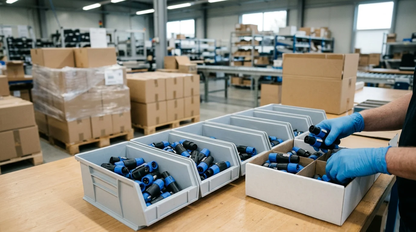
Where can I source OEM 4-pole Speakon cables for bi-amp systems?
JINGYI Audio supplies OEM/ODM Speakon connectors and premade speaker cables, with OFC copper, automated assembly, and private-label options for pro-audio brands and installers.


