Introduction
In professional audio, cable choice affects far more than convenience: it shapes noise performance, reliability, and system consistency. XLR cables became the standard because their three-pin, balanced design helps reject interference, preserve signal integrity over long runs, and provide secure connections in demanding environments such as studios, stages, and broadcast facilities. This article explains how XLR cables work, why balanced transmission matters, and what makes them better suited than common consumer connectors for critical audio paths. By the end, you’ll understand the practical and technical reasons XLR remains the default solution across modern professional sound systems.
Why XLR Cables Matter in Professional Audio
Professional audio infrastructure relies heavily on robust, interference-free signal routing to maintain fidelity across complex signal chains. At the center of this ecosystem is the XLR connector, a standardized termination that dictates the physical and electrical integrity of analog and digital audio networks.
Unlike consumer-grade unbalanced connections, the XLR architecture is engineered to isolate signal transmission from harsh electromagnetic environments, making it indispensable for recording studios, broadcast facilities, and large-scale touring productions.
How XLR cables reduce risk in live sound
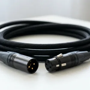
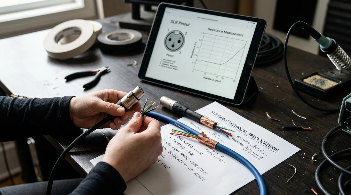
The primary operational advantage of the XLR ecosystem in live environments is its deployment of balanced audio architecture. By utilizing three pins—ground, positive (hot), and negative (cold)—XLR cables transmit two identical signals in opposite polarity. Upon reaching the differential amplifier at the destination, the polarity of the negative signal is inverted, summing the original audio while actively canceling out any noise picked up along the cable run.
This phase-cancellation phenomenon is measured by the Common-Mode Rejection Ratio (CMRR). In high-quality professional audio systems, the CMRR often exceeds 80 dB to 100 dB, virtually eliminating electromagnetic interference (EMI) and radio frequency interference (RFI) even over continuous cable runs exceeding 300 feet (90 meters). Additionally, the mechanical locking mechanism of standard XLR chassis connectors provides a retention pull force of up to 50 lbs (22 kg), mitigating the risk of accidental disconnects during high-kinetic stage performances.
Why XLR became the industry standard
Originally developed by Cannon Electric in the mid-20th century—starting as the 'Cannon X' series, later adding a latch ('L') and a synthetic rubber compound ('R')—the three-pin XLR evolved into the definitive standard formalized under the IEC 61076-2-103 specification.
This strict international standardization ensures absolute cross-manufacturer compatibility. Audio engineers can interface a microphone manufactured in Germany with a mixing console built in Japan using cabling sourced from the United States, confident that the pinout, impedance handling, and mechanical mating cycles will align flawlessly. The ubiquitous nature of this standard has driven economies of scale, allowing highly sophisticated balanced cabling to become cost-effective for mass deployment across global production networks.
Core Technical Factors in XLR Cables
A comprehensive understanding of XLR cable performance requires analyzing the interplay between its internal geometry, conductor materials, and shielding methodologies. These technical variables directly dictate the cable's capacity to preserve transient response and frequency linearity.
How pin configuration, shielding, and conductors support balance
d audio
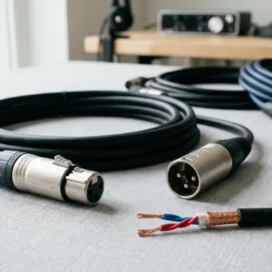
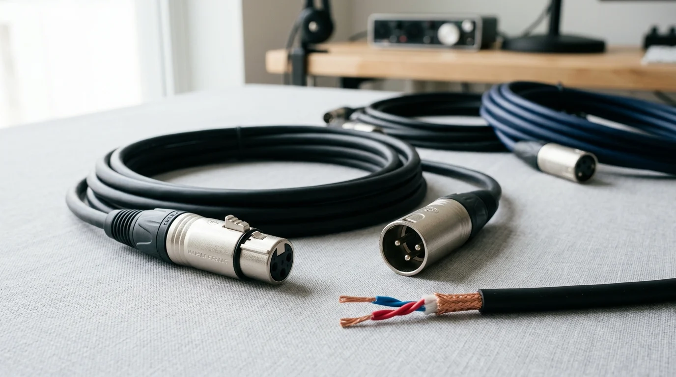
The standardized pinout—Pin 1 designated for shield/ground, Pin 2 for the positive signal, and Pin 3 for the negative signal—forms the mechanical basis of balanced signal transmission. Professional-grade cables typically employ Oxygen-Free Copper (OFC) conductors, generally specified between 20 AWG and 24 AWG, to minimize electrical resistance over long distances.
Shielding strategies further define performance capabilities. Braided copper shielding offers superior durability and up to 95% physical coverage, making it ideal for high-flex stage applications. Conversely, foil shielding provides 100% coverage against high-frequency RFI but lacks the mechanical resilience for repeated coiling, relegating it primarily to permanent studio installations.
When to use microphone, line-level, and AES/EBU XLR cables
While analog microphone and line-level signals operate over identical XLR topologies, the electrical demands differ significantly. Analog microphone signals operate at nominal low-voltage levels, typically between -60 dBu and -40 dBu (millivolts), requiring pristine shielding to prevent noise floor amplification. Line-level signals, utilized between outboard gear and active monitors, drive much higher voltages, frequently pushing up to +24 dBu (12.28 Vrms).
Digital audio transmission necessitates strict adherence to distinct electrical tolerances. AES/EBU (AES3) digital audio utilizes the standard 3-pin XLR form factor but requires a specific 110-ohm characteristic impedance with a tight tolerance of ±10%. Using standard analog microphone cables for AES/EBU digital signals introduces impedance mismatches, resulting in signal reflection, timing jitter, and eventual data dropouts.
| Parameter | Standard Analog XLR | AES/EBU Digital XLR |
|---|---|---|
| Characteristic Impedance | Variable (Not critical) | 110 Ω (±10%) |
| Nominal Capacitance | 20–45 pF/ft | <15 pF/ft |
| Conductor Gauge | 20–24 AWG | 24–26 AWG |
| Maximum Effective Range | >300 ft (90 m) | 328 ft (100 m) |
Common failure points in low-quality XLR cables
Inferior manufacturing processes often manifest in elevated parasitic capacitance, which acts as an unintended low-pass filter. Capacitance exceeding 30 pF/ft (picofarads per foot) will induce noticeable high-frequency roll-off, dulling the audio signal on extended runs.
Mechanical failures are equally prevalent in budget-tier cables. Cold solder joints at the terminal cups increase contact resistance and introduce intermittent signal dropouts. Furthermore, inadequate internal strain relief allows external tension to pull directly on the delicate solder points, rapidly accelerating conductor fatigue and eventual failure.
How to Compare XLR Cable Build Quality
Procurement of XLR cables requires shifting focus from basic electrical continuity to rigorous mechanical build quality. The tactile, metallurgical, and physical properties of a cable directly dictate its lifecycle value and operational reliability in mission-critical environments.
Key criteria for comparing XLR cables
Connector metallurgy and internal strain relief design are paramount criteria for evaluation. Premium connectors utilize chuck-type strain relief systems that clamp down uniformly on the cable jacket, distributing tension evenly and preventing conductor separation. In contrast, inferior crimp-style strain reliefs can puncture the jacket or deform the internal dielectrics over time.
Contact plating heavily influences long-term performance. While silver plating offers superior baseline conductivity, it is highly susceptible to tarnishing and oxidization in humid environments. Consequently, 24k gold plating—typically applied at a precise thickness of 0.2 microns—is the preferred standard for professional applications, providing excellent conductivity alongside total immunity to corrosive degradation.
How durability, repairability, and phantom power handling affect
value
Microphone preamps routinely supply +48V DC phantom power (standardized via IEC 61938) down pins 2 and 3 to operate condenser microphones and active direct injection (DI) boxes. While the current draw is minimal, typically capping under 10 mA per channel, a short circuit in a poorly manufactured cable can cause electrical arcing, permanently damaging sensitive preamp input stages.
Serviceability is a crucial value multiplier. High-quality XLR connectors feature modular, thread-locked housings that allow technicians to open the connector, inspect the solder cups, and perform field repairs. Riveted or permanently molded connectors offer zero repairability, forcing operators to discard the entire cable assembly if a single solder joint fails, severely diminishing the long-term return on investment.
How to Specify, Source, and Deploy XLR Cables
Effective deployment of audio cabling extends beyond individual specifications, requiring a systemic approach to specification matching, routing logistics, and inventory management. Properly engineered infrastructure minimizes troubleshooting time and maximizes system stability.
How to match cable length, flexibility, and ruggedness to
the application
Matching cable geometry to the specific acoustic and physical environment is critical for maintaining signal integrity. In high-noise environments characterized by dense lighting rigs, LED walls, and heavy power distribution, star-quad cables are heavily favored. Star-quad geometry utilizes four tightly twisted conductors rather than two, which exponentially increases common-mode rejection, yielding an additional 20 dB to 30 dB of noise reduction compared to standard twisted pairs.
For touring applications, the outer jacket material dictates longevity. Polyurethane (PUR) jackets provide superior abrasion resistance, chemical tolerance, and remain pliable in sub-zero temperatures, often rated to withstand upwards of 10,000 extreme bending cycles without structural failure.
| Deployment Scenario | Recommended Geometry | Jacket Material | Shielding Requirement |
|---|---|---|---|
| Studio / Fixed Installation | Standard Twisted Pair | PVC | Foil (100% coverage) + Drain Wire |
| Live Stage / Touring | Star-Quad (4-conductor) | Polyurethane (PUR) | Braided Copper (>95% coverage) |
| Broadcast / High-RF Area | Star-Quad (4-conductor) | Heavy-duty PVC | Double Braided Copper |
Best practices for inspection, testing, labeling, and inventory
control
Operational reliability hinges on stringent inventory control and proactive testing protocols. Prior to deployment, cables must be subjected to automated cable testers to verify pin-to-pin continuity, phase coherence, and the absence of micro-shorts between the chassis and ground.
Enterprise-scale audio providers utilize rigorous labeling systems, employing transparent heat-shrink tubing over custom barcodes and length indicators to track asset depreciation and simplify strike times. When specifying infrastructure for large venues, purchasing managers often rely on bulk sourcing, where minimum order quantities (MOQs) of 1000-meter spools are custom-terminated in-house to precise lengths, dramatically reducing cable slack and rack clutter.
Decision Framework for Choosing XLR Cables
Selecting the optimal XLR cabling infrastructure is a strategic investment that balances upfront capital expenditure against long-term operational stability. A rigorous decision framework prevents the costly pitfalls of under-specification and the unnecessary overhead of over-specification.
Which specifications and purchasing criteria should guide final
selection
A robust purchasing framework evaluates cost-per-foot alongside critical electrical metrics such as nominal capacitance, shield coverage percentage, and conductor AWG. Buyers should mandate verifiable specification sheets from manufacturers, targeting an out-of-box defect rate of less than 0.1%.
Connectors must be sourced from established industry vendors with proven track records for metallurgical consistency. By establishing baseline thresholds—such as requiring >90% braided shielding for all stage cables and mandatory gold-plated contacts for permanent patch bays—procurement teams can filter out substandard products that threaten system stability.
How standardization supports long-term interoperability
Standardization across a facility or touring rig ensures seamless interoperability and minimizes troubleshooting downtime. By committing to a unified ecosystem of high-grade connectors and specific cable topologies, audio engineers can rapidly swap components without introducing variable impedances or differing capacitance loads.
While premium XLR cables carry a higher initial procurement cost, their superior flex life, repairability, and consistent electrical performance yield a significantly lower total cost of ownership. A meticulously specified and standardized XLR inventory will routinely deliver a functional lifespan of 10 to 15 years, cementing its status as the foundational bedrock of professional audio engineering.
Key Takeaways
- The most important conclusions and rationale for XLR Cables Explained
- Specs, compliance, and risk checks worth validating before you commit
- Practical next steps and caveats readers can apply immediately
Frequently Asked Questions
Why are XLR cables preferred over unbalanced audio cables?
XLR cables use balanced wiring on three pins to cancel noise and hum. They also lock securely, making them more reliable for live sound, studios, and broadcast setups.
Can I use any 3-pin XLR cable for AES/EBU digital audio?
No. AES/EBU needs a 110-ohm XLR cable. A standard analog mic cable may pass signal, but it can cause reflections, jitter, and dropouts on longer runs.
What should I look for in a high-quality XLR cable?
Choose OFC copper conductors, strong strain relief, durable connectors, and effective shielding. For stage use, braided shielding is usually best because it handles repeated flexing better than foil.
How long can an XLR cable run without major signal problems?
Analog balanced XLR runs often work well beyond 300 feet in proper systems. For AES/EBU digital, keep runs within about 328 feet and use true 110-ohm cable.
Can JINGYI provide custom XLR cables for OEM or private label projects?
Yes. JINGYI offers OEM/ODM and private label XLR cable production, including custom lengths, connector options, and pro-audio solutions for studios, live events, cinemas, and system integrators.